Changing Dashboard Cluster Lights
How-To for BMW F models
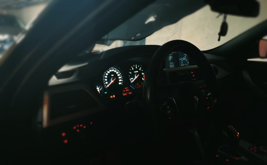
Are you bored of your BMW's orange speedometer light? That's understandable. Here we show you step by step how you can change your speedometer illumination to your desired color without having to dig deep into your pockets.
The cost of speedometer lighting modifications by tuning companies ranges from €150 to €250, depending on the car model. It therefore makes sense to take on the project yourself, which not only saves money, but also gives you the ability to make future adjustments for your friends. Have fun with the instructions!
- How to change the Dashboard Cluster Lights?
- Required Tools & Components
- Step 1: Remove the Dashboard Cluster
- Step 2: Disassemble Cluster & Identify LEDs
- Step 3: Desoldering SMD LEDs
- Step 4: Solder in new SMD LEDs
- Step 5: Wrap the pointers & Assemble the Cluster
- Step 6: Re-install and Test the Dashboard Cluster
- Conclusion & Before/After photos
- More Articles
How to change the Dashboard Cluster Lights?
It is often claimed that the color of the dashboard cluster lights could be recoded. For some newer car models with a digital display speedometer, this is certainly the case. In these speedometers, switching through the onboard computer is usually already factory-enabled.
The dashboard cluster lights in BMW F models (and older) can only be changed by desoldering the old SMD LEDs and soldering in new SMD LEDs.
While it sounds more difficult than it actually is, it only requires a bit of practice with the soldering iron. In this detailed guide, you will learn which tools and components are perfect for changing the dashboard cluster lights and how to become a pro with the soldering iron!
If you have never used a soldering iron before, we recommend purchasing a practice board. These usually cost less than €10 and include various SMD types for soldering and practice. Soldering itself is not difficult, as you will discover while practicing. Here, you will find a practice board that offers more than enough hands-on experience needed for tasks like changing the dashboard cluster lights.
- Dieses tolle DIY-Kit ist eine großartige Schweißübungsplatte, um Ihr Erlebnis zu verbessern und…
- Die linken und rechten drei Spalten von Komponenten werden verwendet, um das Schweißen zu üben,…
- Die Rückseite des Schaltkreises wird ebenfalls verwendet, mit einem Lineal, um die Messung von…
- Schließen Sie nach dem Schweißen einfach Strom (3-12V) an, um den Effekt zu sehen. Sie können den…
Required Tools & Components
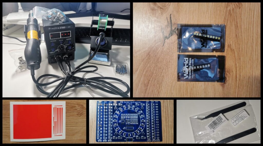
Depending on which method you prefer for resoldering the dashboard cluster lights, you will need a suitable soldering station. If you choose the classic method, a station with just a soldering iron will suffice. If you prefer the hot-air method, you will need a soldering station with a hot-air soldering iron. For both methods, one thing is especially important: adjustable temperature and various soldering tips. Here are two affordable and reliable soldering stations that we use ourselves:
- PID temperature control technology: Integrated into the most advanced...
- Anti-static design: Prevents static electricity or electrical dispersion from...
- NO WINDSHIELD: If the heat gun stops abnormally, the program switches off automatically....
- Digital temperature correction: If the environment is influenced or the heating element is...
- [High efficiency soldering station]: 60W soldering iron, fast heating ceramic core, high power temperature...
- [LCD digital display]: Easy-to-read LCD display, spiral temperature adjustment button for...
- [Constant temperature control]: PID (Proportional Integral Derivative) technical program is...
- [Intelligent sleep mode]: After 10 minutes of inactivity, the soldering station automatically switches to...
Of course, you will also need accessories. When it comes to soldering, the possibilities are endless. Everything from a soldering mat to a microscope can be helpful. However, we have compiled the essentials you need for changing or resoldering the dashboard cluster lights.
*Affiliate links, information in footnote or here.
When it comes to components, they are essentially limited to the new SMD LEDs in your desired color and the pointer foils. For the lighting, we chose the color white, and for the pointers, the color red. The speedometers of BMW F models use standard type 3528 PLCC SMD LEDs. These are inexpensive and widely available. Alternatively, 0805 LEDs can also be used.
You can save money on the pointer foils by cutting the transparent color foil yourself. However, if you prefer to save time instead of money, we recommend the pre-cut pointer foils from BLUTEC.
The white SMD LEDs and the pointer foils that we use to change the speedometer lighting can be found here:
*Affiliate links, information in footnote or here.
Step 1: Remove the Dashboard Cluster
The very first step is, of course, to disconnect the battery in your vehicle. It is generally always recommended to disconnect the battery when working on electrical components to prevent error codes.
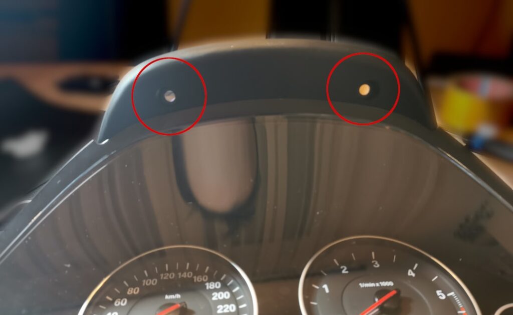
Removing the speedometer may be a bit tight, but it is still easy and quick to do. First, remove the two Torx screws on the top of the dashboard cluster cover.
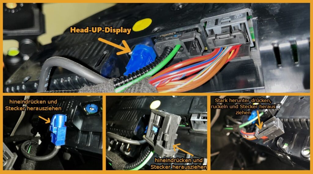
Next, pull the speedometer out as far as the cables and the steering wheel allow. It is helpful to extend your adjustable steering wheel fully as well. This creates more space to reach behind the dashboard cluster. You will find a total of 2 connectors, both of which have a lock. If you have a head-up display, there will be a total of 3 connectors with locks. You need to unlock and pull them out. See the following image for reference:
Next, pull the speedometer out and place it on the table. It will be easier if you first slide the top edge of the speedometer over the steering wheel. This will make it much easier to pull the entire dashboard cluster out.
Step 2: Disassemble Cluster & Identify LEDs
Changing the BMW dashboard cluster lights in this step requires disassembling the speedometer and identifying the SMD LEDs that need to be replaced.
Remove the cover:
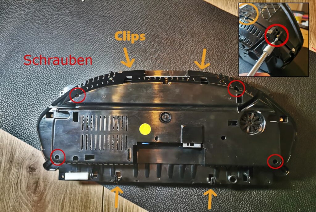
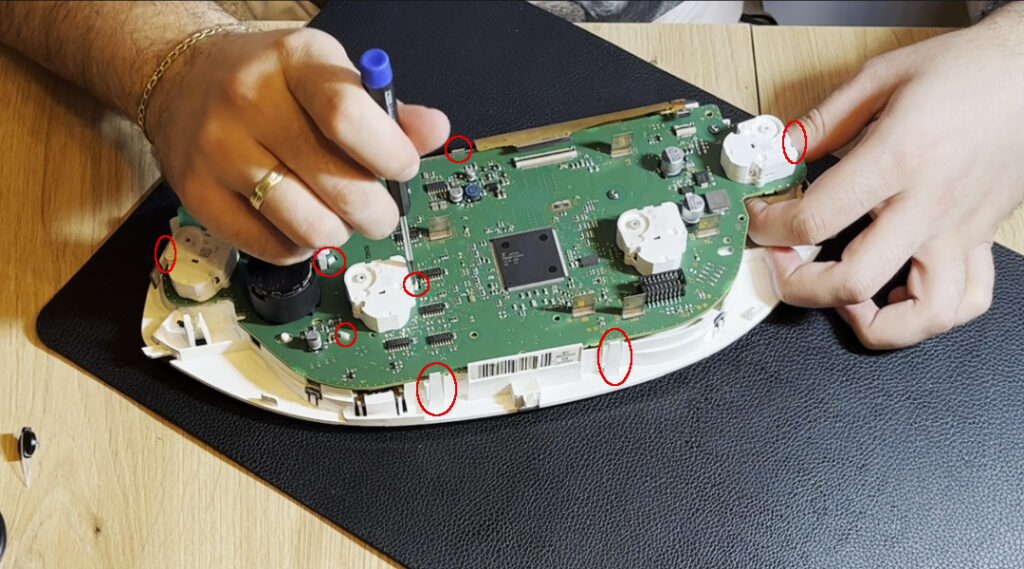
You can now carefully remove the outer cover of the speedometer. The cover is held in place by a total of 6 easily "snap-off" clips around the speedometer and 4 small Torx screws. A narrow plastic spatula and a thin Torx screwdriver will help you gently release the cover.
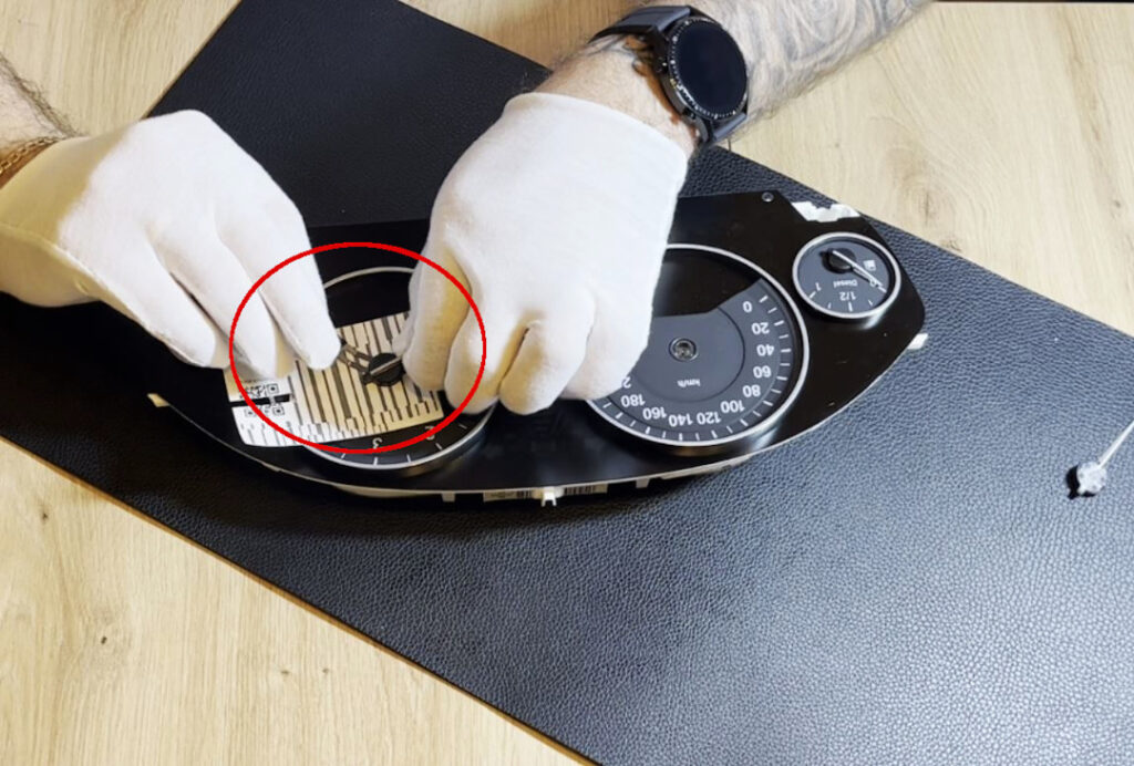
Lever out the pointer:
Remove the pointers by carefully prying them off. Keep in mind that the pointers are mounted on inserted shafts. For older models (around 2012 or earlier), be careful when prying off the dashboard needles to ensure that the speedometer cable at the back doesn't come loose.
In our example, this is not the case. Here, you can simply lift the dashboard needles without any concerns. They are relatively firmly in place, so feel free to apply a bit more leverage. However, be careful not to scratch the cluster glass and place a protective layer on the glass. A levering tool is very useful here.
Unplug the rear circuit board:
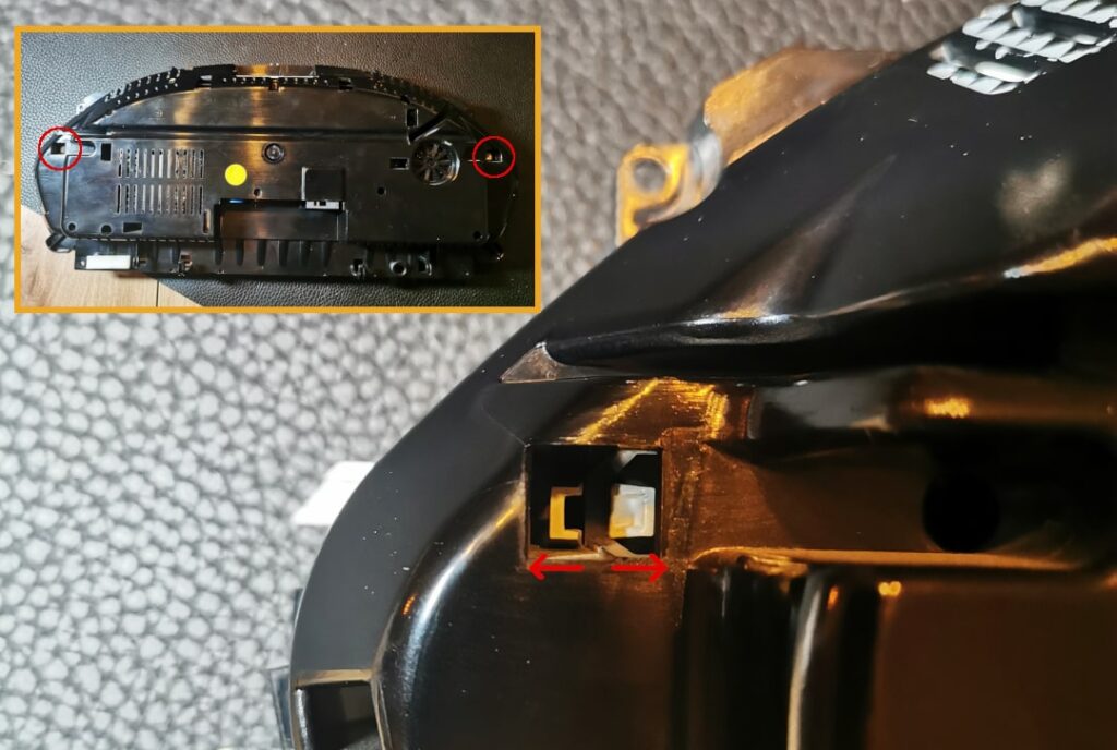
After removing the dashboard needles, you can now unclip the rear cover. It is unlocked by pressing the white clips in as shown in the photo. You will then hear a "click" and can easily pull off the plastic casing.
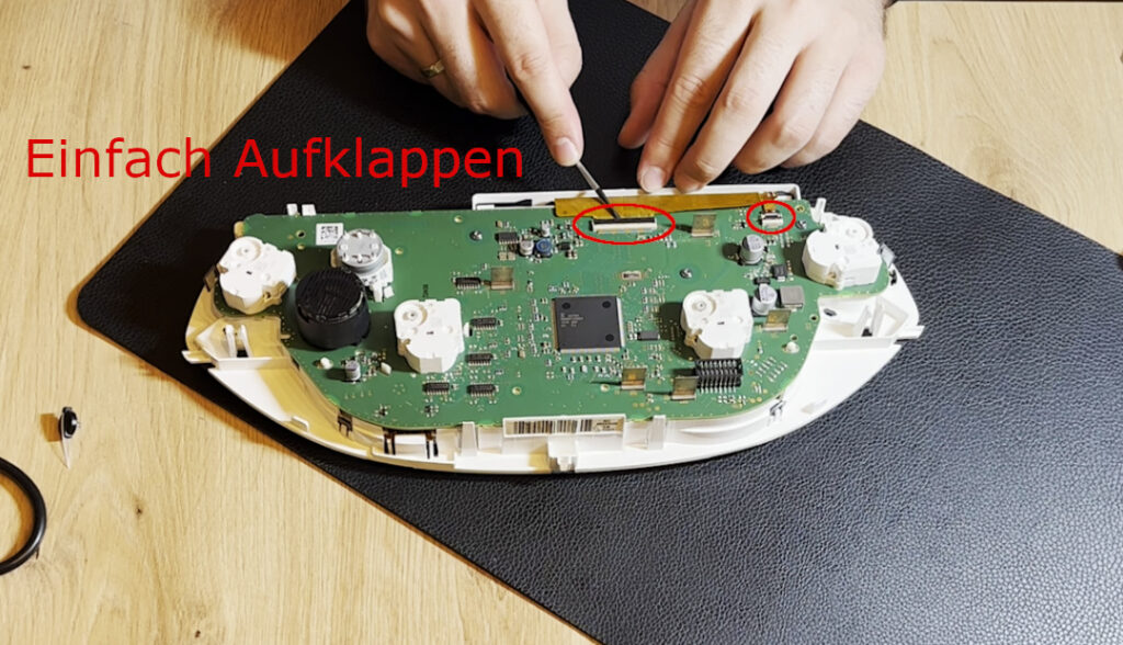
Loosen ribbon connector & remove circuit board
Remove the second, or rear, circuit board by disconnecting the ribbon connectors and unclipping them from the respective holders. Theoretically, you wouldn’t need to disconnect the ribbon cable at all; you could simply flip the second circuit board over. However, it will make your work much easier if you can set the second board aside. This also reduces the risk of damaging the ribbon cable while working.
Next, you can separate the circuit board from the rest of the unit by unlocking the white clips as shown in the following photo:
Which SMD LEDs should be replaced?
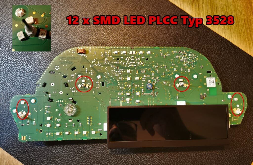
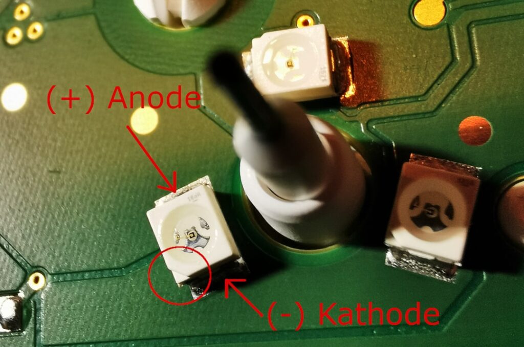
Typically, these are the LEDs that are placed around the dashboard needles. In most cases, including here with the F30, there are 3 SMD LEDs per speedometer wire. These are the ones that need to be replaced. In principle, the speedometer construction is the same for all F models. What you must not forget is to mark the negative poles of the LEDs on the circuit board. SMD LEDs have both positive and negative sides and will not work if soldered in the wrong direction later.
Step 3: Desoldering SMD LEDs
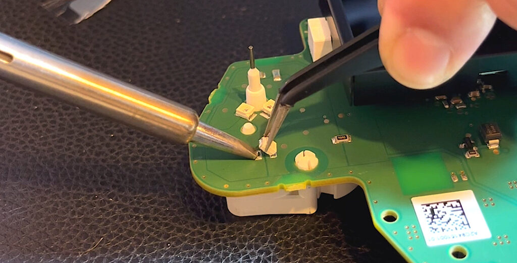
Desoldering the original SMD LEDs starts by setting the soldering iron to at least 360°C. We wouldn’t recommend setting it any higher for this task. The soldering tip is generally not important, but you can make the soldering process easier by choosing a soldering tip that is the same width as the soldering point itself. This way, the heat can be distributed evenly.
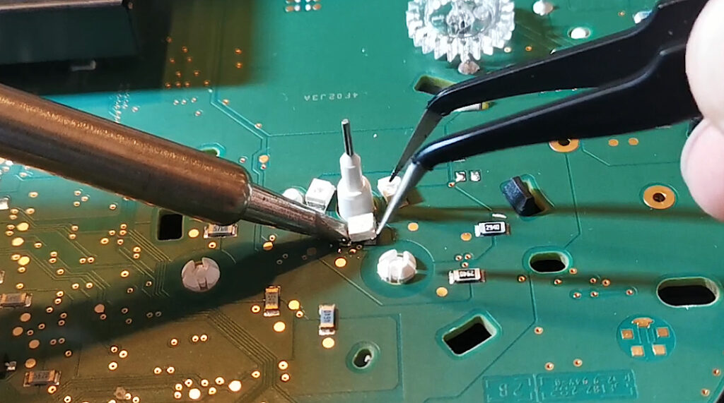
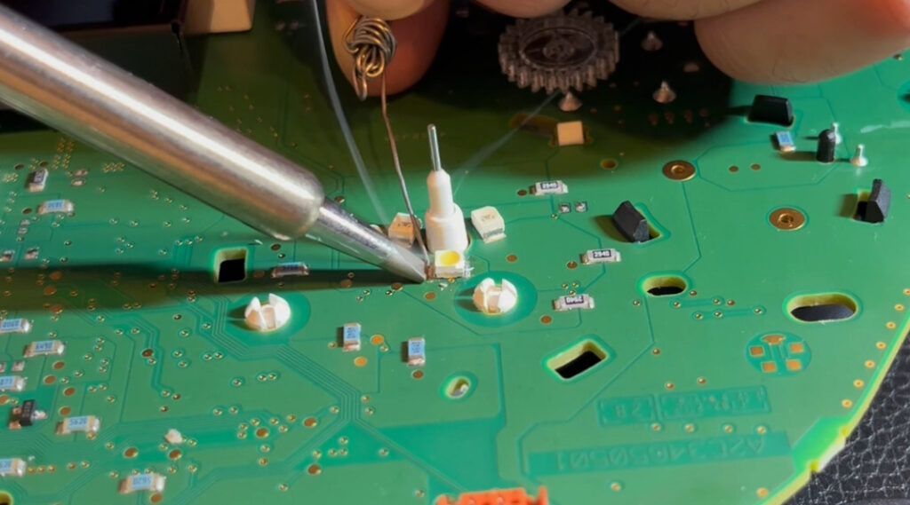
First, you only loosen one side of the LED and pry it open with the tweezers. Be patient here, as these solder joints were machine-made and can withstand quite a bit of heat. If you are unable to melt the solder joint, simply add some fresh solder to the soldering iron and try again.
In principle, there is no solder joint that cannot be undone. With this BMW dashboard cluster, we had to add solder to almost every solder joint to get them undone.
Once the first side is freed, you can fold it back down with your finger and go through the same procedure on the second side.
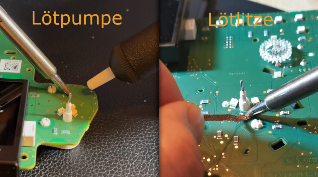
Next, clean the solder joint a bit. You can either do this with a solder pump (heat the solder and pump it out) or with a copper braid. Fresh solder is always better than the solder that was originally on the circuit board.
Step 4: Solder in new SMD LEDs
When soldering the new white SMD LEDs for the dashboard lighting, set the soldering iron to no higher than 360°C. This temperature is ideal for beginners and this type of project. It’s important that you always position the circuit board in a way that is most comfortable for you.
If necessary, use some tape or a non-slip mat to secure the circuit board. As mentioned in the previous chapter, by now you should be more familiar with the soldering iron thanks to the practice board. Now, let's get started with the actual changing of the dashboard lighting.
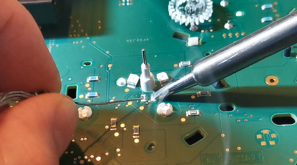
First, tin one of the two solder pads (solder joints). To do this, briefly heat one of the solder joints and then immediately add some solder.
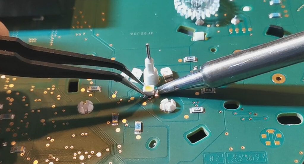
The next step is to hold the new SMD LED with the tweezers in such a way that you can easily slide it onto the previously tinned solder joint while lifting the soldering iron to the LED and the solder joint at the same time. You will then melt the solder again and slide the new LED onto the solder joint while the solder is still liquid.
Now that the first solder joint is done, turn the dashboard circuit board so that you can access the second solder joint in the same way. As with the first solder pad, briefly heat the solder joint and then add the solder. Done.
You will repeat this procedure for all 12 SMD LEDs of the dashboard lighting. The important thing here is to stay calm and not stress yourself out. Even if you soldered poorly once, it's no big deal. Just repeat the process (desoldering-resoldering) and take your time. The circuit boards and LEDs can handle more than you think. However, you should still handle the soldering iron carefully to avoid damaging the circuit board.
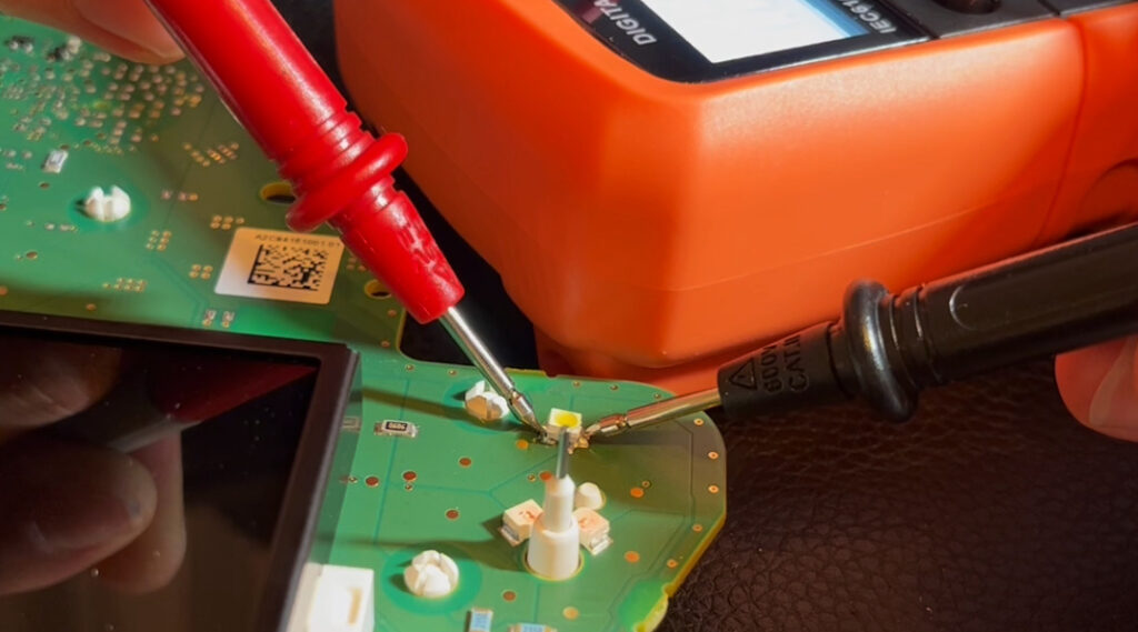
Test new LEDs with a multimeter
To test an SMD LED with a multimeter, select the diode test function. Identify the anode (+) and cathode (-) of the LED and connect the red probe to the anode and the black probe to the cathode. A working LED should cause the multimeter to show continuity or emit a beep.
Some multimeters also have a low voltage diode test, which would cause the intact LED to light up. However, the diode voltage must be high enough to make the LED light up. This means that a non-lighting LED does not necessarily indicate that it is not working.
During the continuity test, however, the multimeter should display a value that is not 0. Otherwise, you can most likely assume that either the LED or your multimeter is defective.
Step 5: Wrap the pointers & Assemble the Cluster
Reassemble the two circuit boards by clipping the tachometer board into the second board (the white clips in the middle).
Then insert the two ribbon cables back into position and make sure that the two boards are inserted into each other again. You will hear a soft "click" when the boards have interlocked.
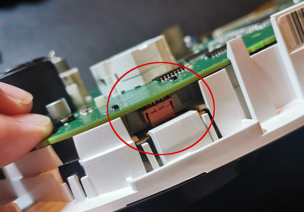
Pay attention to the red cruise control connector on the top side. It’s easy for the red connector to not be properly plugged in when reassembling the boards. If that’s the case, you can easily help with your hand or tweezers to gently push the connector in.
Once you’ve done everything up to this point, don’t forget to clean the display and the tachometer dial. You won’t be able to access them later.
Wraping the Cluster Needles
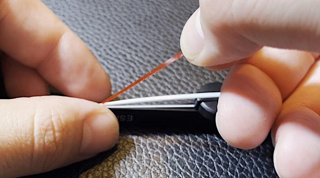
Before you continue reassembling your tachometer, we recommend wrapping your cluster needles. Why wrap and not paint? With paint, there’s a risk that you won’t be able to apply it evenly. As a result, some areas will shine brighter than others.
This can be annoying, but it varies from person to person. It definitely didn’t appeal to us, so we used needle stickers. They’re a bit tricky to apply, but they give you the desired effect.
You can purchase transparent color films in your desired color and cut them individually for each needle, or you can get pre-cut needle stickers. The first method with color films is of course the cheaper option, but it will take you more time and effort. We’ve linked both options for you above in the chapter “Required Tools and Materials”.
Once the needles are wrapped and reinserted, the rear plastic cover is put back on. Then, screw the front bezel back in place with the 4 Torx screws and clean the entire unit again with a cloth. Your speedometer with updated lighting is now ready to be installed back into the car.
Step 6: Re-install and Test the Dashboard Cluster
Simply insert the fully assembled speedometer unit back into the groove from the top and reconnect the plugs. Done. We recommend testing the speedometer unit before tightening the two Torx screws at the top of the bezel. Reconnect the car battery and check the following points:
If everything works, you can tighten the two Torx screws and take a short test drive, at which point nothing should be missing anymore.
Conclusion & Before/After photos
Congratulations! You have successfully changed the dashboard cluster lighting of your BMW F model. This DIY project does require some craftsmanship skills, but with patience and the right tools, you can change your dashboard cluster lighting cheaply and with ease.
Changing the dashboard cluster lighting usually costs between €150 and €250, depending on the car model. Therefore, it's definitely worthwhile to take on this project yourself.
Soldering itself is not difficult, and with some practice using the practice board, you'll have it down in no time! Remember that the tools and methods presented are recommendations – choose the ones that best match your skills.
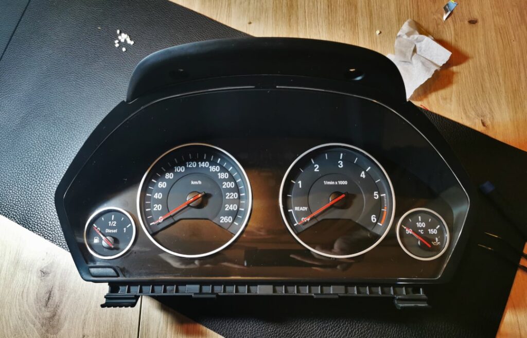
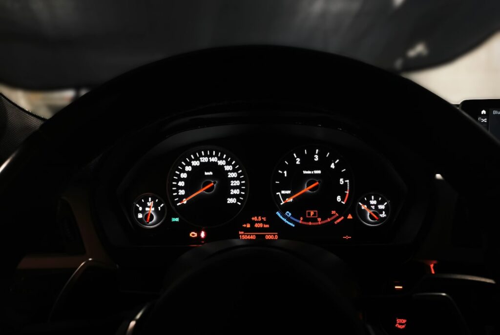
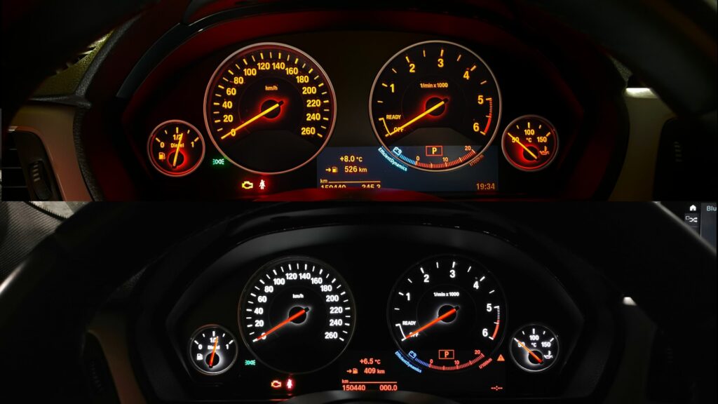
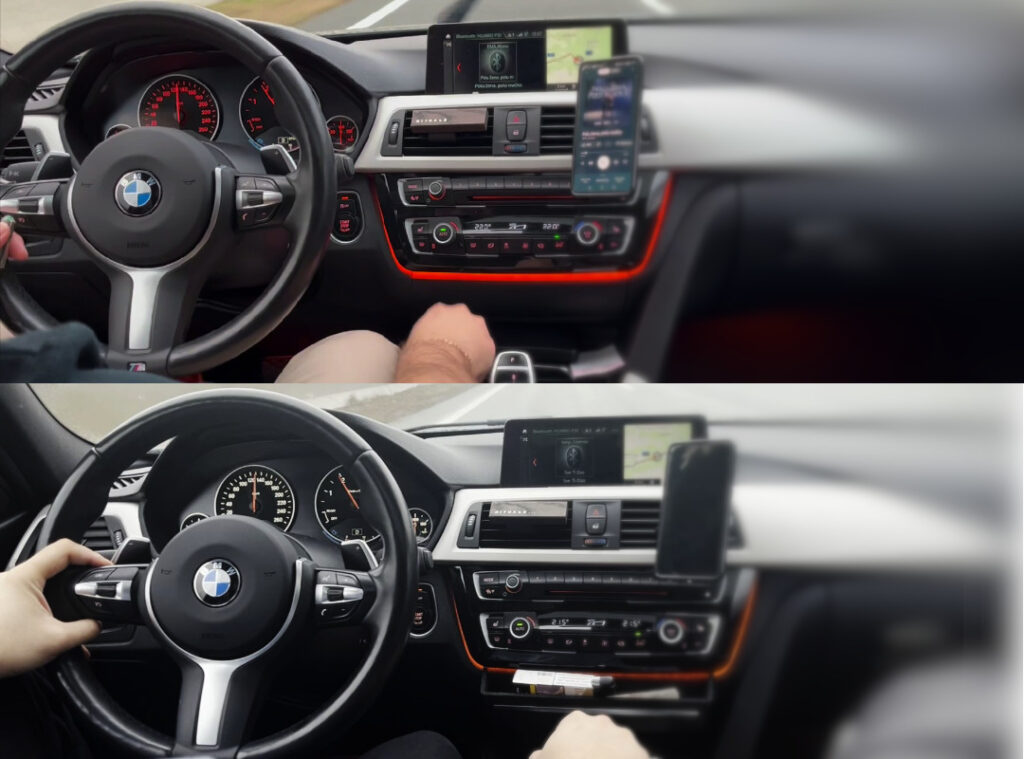
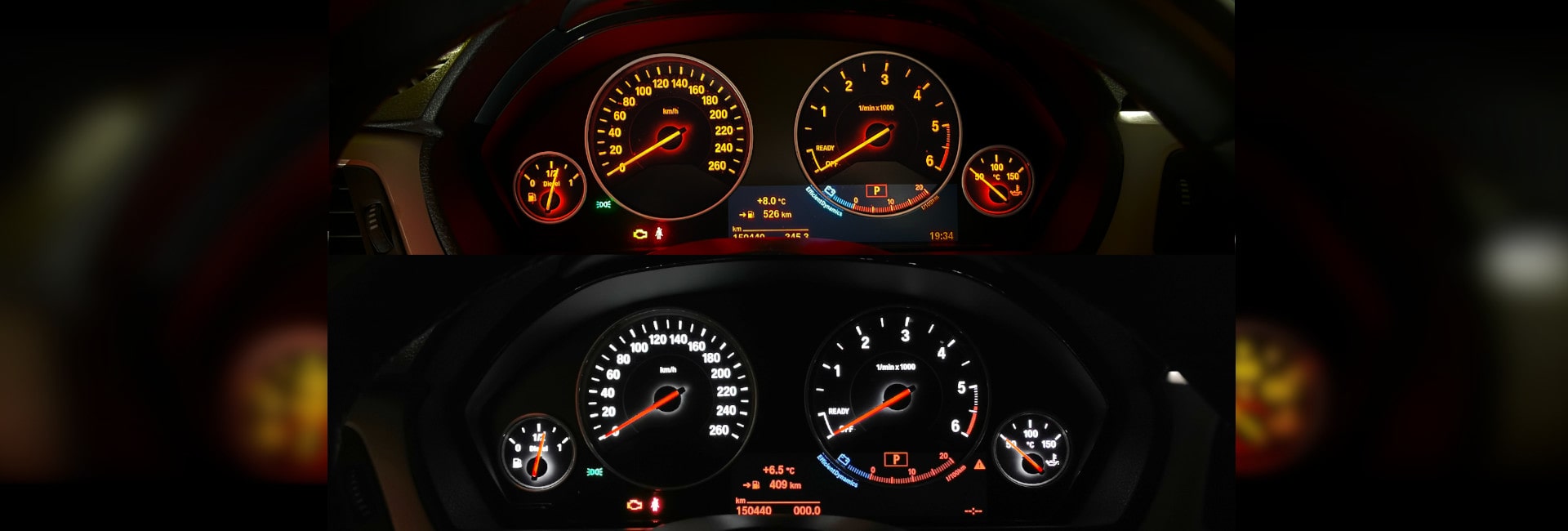
Here we have provided two before/after photos. One before the modification with orange dashboard lighting, and one after the modification with white dashboard lighting and red needles:
* Affiliate links are marked with a *. When you purchase one of these products, we receive a small commission. Nothing changes for you and the offer/price remains the same. You can find more information about affiliate links here.
More Articles
BMW Sport Plus coding: Unlocking driving mode - instructions
BMW Sport & Comfort Plus codingUnlocking driving mode - BMW coding made easy - In this guide you will learn step by step how to...
BMW Emergency Call System Error Battery Replacement | G-Series GUIDE
BMW emergency call system error? solution: change the battery! The well-known BMW emergency call system error (B7F341) occurs in many BMW vehicles, whether E-series,...
Change wheel bearing yourself - INSTRUCTIONS for VW Passat B7
Radlager selber wechselnAnleitung für VW Passat B7 In diesem Beitrag zeigen wir dir, wie du das vordere Radlager an einem…

